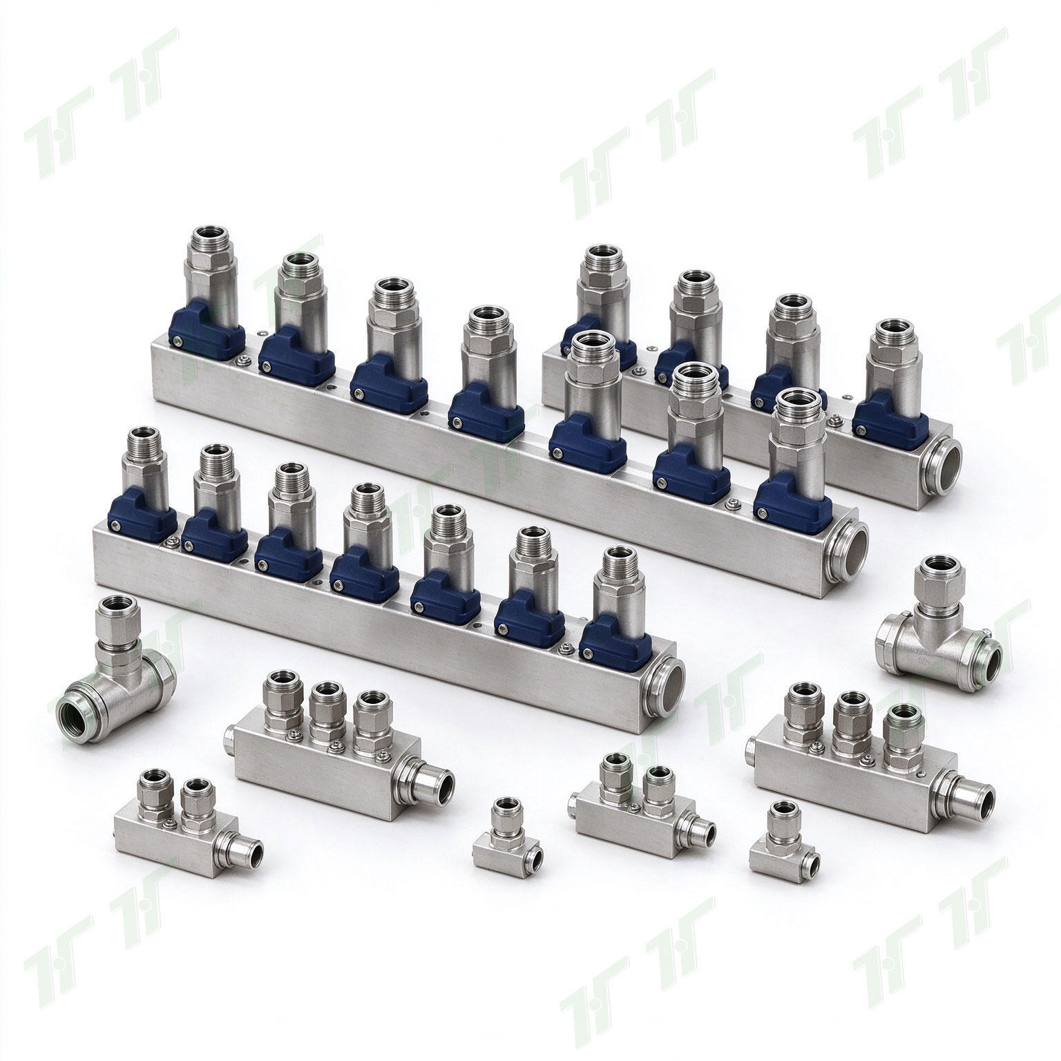
If you have ever assembled a liquid cooling manifold and found that ports did not align, fittings would not seat properly, or flow paths did not match, you have experienced tolerance stack-up.
This article explains what it is, why it matters, and how to manage it.
What Is Tolerance Stack-Up?
Tolerance stack-up is the cumulative effect of individual part tolerances on an assembly.
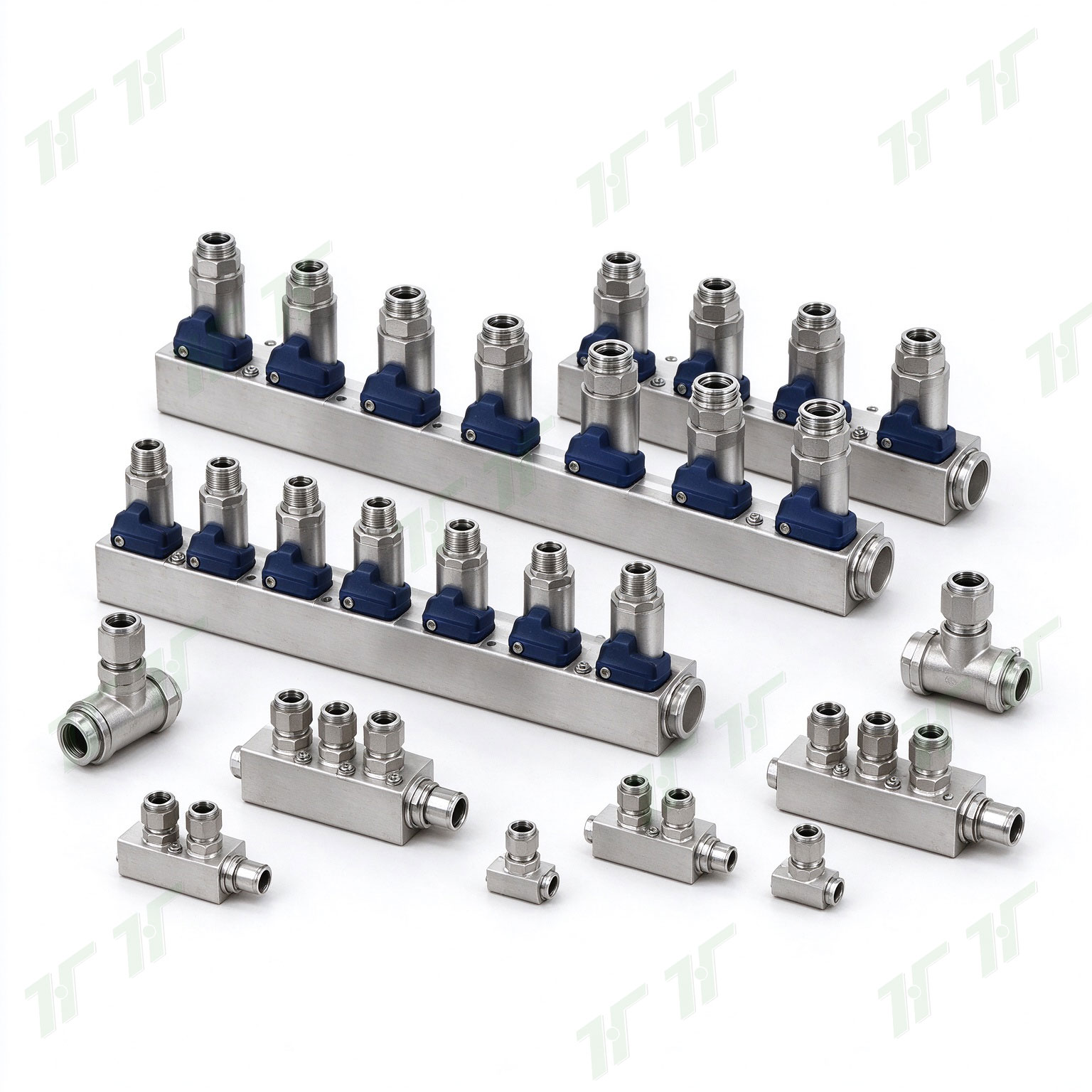
In a manifold assembly, multiple components are connected:
Manifold body
Threaded fittings
O-rings and seals
Adapters
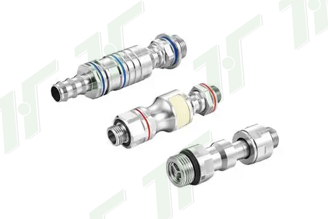
Quick disconnect sockets
Each component has its own dimensional tolerance. When assembled, these tolerances add up — or stack up.
If the stack-up exceeds the design allowance, the assembly may not fit, seal, or function as intended.
A Simple Example
Consider three manifold ports, each with a positional tolerance of ±0.1mm.
| Port | Tolerance |
|---|---|
| Port 1 | ±0.1mm |
| Port 2 | ±0.1mm |
| Port 3 | ±0.1mm |
Worst-case stack-up: ±0.3mm
If the mating component requires alignment within ±0.2mm, the assembly may fail — even though each individual part was within tolerance.
Common Problems from Stack-Up
| Problem | Cause |
|---|---|
| Fittings do not align with rack openings | Positional tolerances stack up |
| O-rings do not seat properly | Bore tolerance + seal tolerance + groove tolerance |
| Threads cross-thread or bind | Thread tolerance + angle tolerance |
| Flow paths are restricted | Internal bore tolerances stack |
| Leak paths develop | Mating surface tolerances stack |
How to Manage Stack-Up
For Design Engineers
1. Identify critical dimensions
Mark which dimensions affect assembly fit. Not every dimension is critical.
2. Specify tighter tolerances on key features
Focus tolerance budgets on sealing surfaces, bore positions, and thread locations.
3. Use GD&T (Geometric Dimensioning and Tolerancing)
Positional tolerances, concentricity, and profile controls are more precise than general tolerances.
4. Perform a stack-up analysis
Calculate worst-case and statistical stack-up before releasing the drawing.
For Procurement and Supplier Management
1. Review supplier capability
CPK ≥1.33 means consistent parts
FAI reports verify first-article compliance
2. Confirm critical tolerances during FAI
The FAI report should show actual measurements on critical features. Verify them against your stack-up calculation.
3. Request CPK data on critical dimensions
CPK confirms the supplier can hold tolerances consistently, not just on the first piece.
Typical Tolerances for Manifold Components
| Feature | Typical Tolerance | Stack-Up Risk |
|---|---|---|
| Port position | ±0.05mm | High |
| Bore diameter | ±0.02mm | Medium |
| Thread position | ±0.1mm | Medium |
| Surface flatness | 0.05mm | Low |
| Overall length | ±0.1mm | Low |
Critical features (port positions and bores) should have the tightest tolerances.
What to Ask Your Supplier
1. "What is your CPK on critical manifold dimensions?"
Aim for CPK ≥1.33.
2. "Do you provide FAI reports with dimensional data?"
FAI confirms first-article compliance.
3. "Can you control positional tolerances to ±0.05mm?"
Confirm capability before ordering.
4. "How do you inspect port locations and bore alignment?"
Inspection methods affect measurement accuracy.
Final Thought
Tolerance stack-up is often overlooked — until parts do not fit.
Design for it. Specify tolerances on critical features. Verify supplier capability through CPK and FAI.
A well-managed stack-up means assemblies that fit, seal, and perform as designed.
Need manifold components with controlled tolerances? Send your drawing for a quote.